
How to Read a Gear Inspection Report: Three Deviation Types, Tolerance Sources and Three Overlooked Judging Details
Gear inspection reports show pitch (fpt, Fp), profile (Fα, ffα, fHα) and helix (Fβ, ffβ, fHβ) deviations per GB/T 10095.1 (ISO 1328-1) or DIN 3962; tolerance values depend on module, diameter, face width and grade.
How to Read a Gear Inspection Report: Three Deviation Types, Tolerance Sources and Three Overlooked Judging Details
Core answer: A gear inspection report comes down to three groups of numbers — pitch deviation (fpt single pitch, Fp total cumulative pitch), profile deviation (Fα / ffα / fHα), and helix (lead) deviation (Fβ / ffβ / fHβ). Accuracy grades are assessed per GB/T 10095.1 (identical to ISO 1328-1) or DIN 3962, and the smaller the grade number, the higher the accuracy. The order of judgement is: first confirm that the datum and the measuring section match the drawing, then compare the allowable values item by item according to module, reference diameter, face width and accuracy grade. Among them, Fp determines indexing accuracy, fHα relates to mesh smoothness and noise, and Fβ relates to load distribution across the face width.
1. The three deviation families on the report, and what gear problem each one corresponds to#
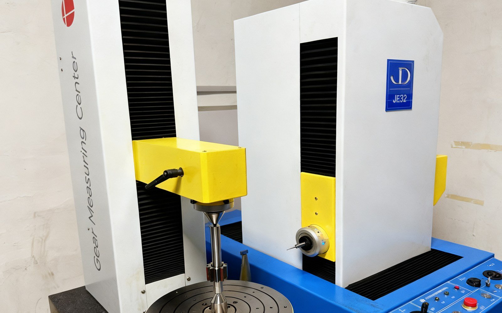
A gear inspection report is the record produced by a gear measuring center that measures the pitch, profile and helix deviations of a finished gear tooth by tooth, and then assesses them against a standard accuracy grade. The three deviation families point to different performance characteristics:
| Deviation family | Common symbols | Meaning | Indicators affected |
|---|---|---|---|
| Pitch deviation | fpt / Fp / fpk | Adjacent pitch deviation, cumulative deviation over one revolution, cumulative deviation over k pitches | Indexing accuracy, uniformity of transmission ratio |
| Profile deviation | Fα / ffα / fHα | Total profile deviation, form deviation, slope deviation | Mesh smoothness, noise, contact stress |
| Helix (lead) deviation | Fβ / ffβ / fHβ | Total deviation across the face width, form, slope | Load distribution across face width, edge loading, tooth-end chipping |
| Radial runout | Fr | Maximum radial variation of the probe during one revolution of the gear | Backlash fluctuation, noise |
Once you can read this table, you have understood half of the report; the remaining question is how tight these values should be held.
2. Allowable values are not fixed numbers: why two suppliers report different figures for the same drawing#
The allowable value of an individual deviation is determined from standard tables according to module, reference diameter, face width and accuracy grade — it is not a fixed number. DIN 3962 specifies the individual tolerances for pitch, profile and helix; GB/T 10095.1 is identical to ISO 1328-1 and specifies the definitions and allowable values for deviations on the same flank of a gear tooth; tooth thickness and backlash are handled separately under DIN 3967. For an approximate comparison of accuracy grades across systems, see Gear Accuracy Standards Explained .
Take helix deviation as an example: the common allowable value for grades 5~7 is roughly in the 6~16 μm range, and the specific value depends on face width and helix angle — the larger the face width, the greater the deviation accumulated from the same angular slope, and the correspondingly looser the allowable value. So when two suppliers report different figures, first check whether they measured the same measuring point on the same datum, and only then talk about being out of tolerance.
3. Three judgement details that are easy to overlook#
1. Fp and fpt are not the same thing. The single pitch deviation fpt is a matter between two adjacent teeth, while the total cumulative pitch deviation Fp is the result of error accumulating over a full revolution. During hobbing, the indexing error of the table worm gear pair accumulates into Fp, showing up as excessive noise at certain positions around the circumference. In applications requiring a uniform transmission ratio, such as indexing mechanisms and multi-station rotary tables, the requirement on Fp is often more critical than on fpt; if a report only gives fpt, then the cumulative problem is invisible.
2. The profile slope deviation fHα converts to a pressure angle deviation. The profile slope deviation describes how much the profile is sloped relative to the theoretical involute and can be converted into a pressure angle deviation; when the tip and root deviate simultaneously, forming a “crown” or a “hollow”, this belongs to the form deviation ffα and reflects the dressing condition of the gear grinding wheel. The core task of grinding after heat treatment is to correct these two quantities back.
3. Are the datum and the measuring section clearly stated? For the same gear, measuring with the bore as the datum and measuring with the journal as the datum can give results that fall into different grades. A report usually has to state the position of the measuring section; for helical gears the normal section at the middle of the face width is generally used; if the drawing specifies transverse tooth thickness and the report gives normal, it is normal for the two figures not to match — convert first, then compare.
4. How to write accuracy requirements into drawings and orders#
- Set the grade: DIN 4~5 for high-speed precision drives, 7~8 for general industrial gearboxes, around grade 9 for low-speed heavy-load;
- Specify all items: pitch, profile and helix must all be specified; specifying only one item means giving up control of the other two;
- Define the datum: make clear the measuring datum (bore or journal) and the measuring section, to avoid differing interpretations between supplier and buyer;
- Define tooth thickness: tooth thickness tolerance and backlash are specified per DIN 3967, written separately from the accuracy grade;
- Agree on the inspection method: gear measuring center or mesh inspection, report with the goods or a designated third party, written into the technical requirements in advance;
- Put the heat treatment process first: carburizing and quenching distortion affects final accuracy, so leave grinding allowance in the process and measure after grinding — do not expect the pre-heat-treatment grade to carry straight through to the finished part.
5. Inspection capability determines how credible the report is#
Measurement capability in turn determines report credibility — if you cannot measure accurately, you cannot assess accurately. The measurement uncertainty of a gear measuring center can reach 0.5 µm, while the profile allowable value of a DIN grade 3 gear is itself on the order of microns; if the equipment capability is insufficient, a measured “pass” is meaningless. CMMs, hardness testers, mesh testers and roundness testers each cover one part of the job; for the specific division of labour see Inspection Methods and Instruments for Precision Gears .
6. What Geyon Transmission can do#
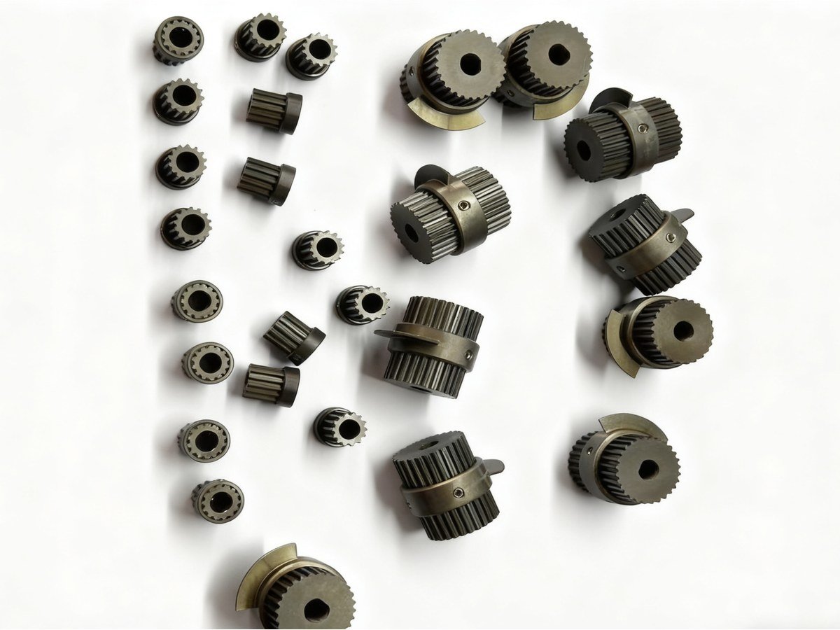
Geyon Transmission machines spur and helical cylindrical gears to drawing (module M0.5–M12, outside diameter within Φ600 mm), with ground accuracy up to DIN 3 and stable batch production at GB grade 4~5; bevel gears are made to GB/T 11365 grade 5~6, worm gear sets cover Z1~Z6 tooth forms, and common materials are 20CrMnTi carburized and quenched (HRC 58~62), 42CrMo quenched and tempered, and 38CrMoAl nitrided. Equipped with gear measuring centers, CMMs, hardness testers and mesh testers, we can measure pitch, profile, helix and hardness and issue reports — see Custom Spur Gears , Inspection and Quality System , Machining Capabilities Overview .
Send over your drawings and operating conditions — module, number of teeth, accuracy grade, heat treatment requirements, application — and after drawing review the engineering team will reply with the process route, inspection plan and quotation. Contact Geyon Transmission or visit the Geyon Transmission website . Only when the grade and datum are clearly marked on the drawing does the inspection report have anything meaningful to compare against.