
What Does Gear Tooth Surface Modification Actually Change? Profile Relief vs Lead Crowning Explained
Profile and lead modification differ from accuracy: ground gears control Fα and Fβ within 10μm to DIN 3, Ra ≤ 0.8μm, 58-62 HRC; modification adjusts contact under load.
What Does Gear Tooth Surface Modification Actually Change? Profile Relief vs Lead Crowning Explained
What gear modification changes is not the accuracy grade, but the “contact position.” Gear grinding controls profile deviation Fα and helix deviation Fβ to within 10μm, which solves whether a single tooth flank is accurate; modification, on the other hand, deliberately removes or adds a few micrometers to several tens of micrometers on the theoretical tooth profile, solving where exactly this pair of gears contacts under load and when the housing deforms, and how they enter meshing. Profile modification addresses the impact and noise at the start and end of meshing, while lead crowning addresses load-induced misalignment and tooth-end stress concentration under load. The two do not conflict: a good tooth flank is first achieved through gear grinding, and then the contact zone is tuned to the service state through modification.
In one sentence: Gear grinding governs “whether the tooth profile is correct,” while modification governs “whether the contact is good.”
I. First distinguish three concepts, don’t mix them up#
When communicating about gears, “accuracy,” “modification,” and “chamfering” are often treated as the same thing, but they actually answer three different questions:
| Concept | English | What is changed | Purpose | Who determines it |
|---|---|---|---|---|
| Profile / lead accuracy | Profile / Lead accuracy | The amount by which the tooth flank deviates from the theoretical profile | Whether a single tooth flank is machined accurately | Grinding process, machine tool, grinding wheel |
| Profile / lead modification | Profile / Lead modification | The shape deliberately added or removed on the theoretical profile | Contact position and smoothness under load | Design calculation, service conditions |
| Tooth-end chamfering / edge break | Chamfering / Edge break | Sharp corners at tooth ends | Deburring, preventing knocks, facilitating assembly | Process habit |
The first two both act on the tooth flank, but one is “approaching the theoretical value,” and the other is “intentionally deviating from the theoretical value.” If mixed up, the customer will think modification is a machining error.
II. Profile modification: governing the impact at the start and end of meshing#
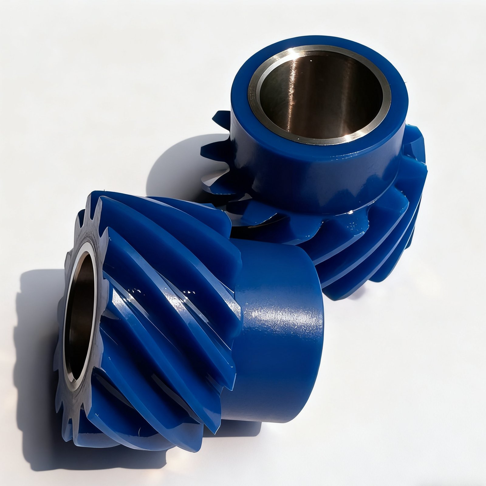
Profile modification refers to the practice of deliberately removing a small segment of material along the profile direction near the tooth tip or tooth root, the most common being tip relief.
When a gear first enters meshing and is about to exit meshing, the deformation of the loaded tooth pair and base pitch error cause the actual contact point to deviate from the theoretical position, and the tooth tip edge bears the load first, producing impact and noise. Tip relief means leaving a tiny “clearance” segment at the tooth tip.
| Modification position | Common practice | Problem solved | Application |
|---|---|---|---|
| Tip relief | A small segment of profile at the tooth tip removed by several micrometers to several tens of micrometers | Meshing-in impact, meshing noise | High speed, low noise requirements |
| Root modification | Corresponding segment at the tooth root given clearance | Meshing-out impact | Often used in pair with tip relief |
| Symmetric tip + root | One segment modified at each end | Bidirectional transmission, forward and reverse | Reducers, robot joints |
How much relief to give depends on module, load, and speed. The larger the module and the higher the load, the greater the clearance; on the same piece of equipment, using the same relief amount for M2 and M8 teeth often means one end has no effect while the other end weakens load capacity. The relief amount must be calculated for the specific gear; do not apply a fixed value.
When a customer complains of “high-speed whine that disappears when speed is reduced,” do not rush to change the material: after confirming that the center distance and profile deviation are acceptable, check whether the tooth tip has no relief, or whether the relief amount is too small — this kind of high-frequency whine is often meshing-in impact, not insufficient tooth flank accuracy.
III. Lead modification: governing misalignment under load#
Lead modification refers to the practice of changing the tooth flank along the face width direction, the most common being lead crowning, i.e., making the tooth flank slightly convex in the middle along the face width direction.
Ideally, contact along the face width direction should be uniform across the full width. But under actual load, the shaft bends and the housing deforms; as soon as the load comes on, the two ends of the tooth flank contact first, while the middle actually separates, and the contact zone becomes narrow strips at both ends: tooth-end stress concentration, which also brings out noise and early pitting.
| Load state | Contact of unmodified tooth flank | Contact after lead crowning | Result |
|---|---|---|---|
| No load | Full-width line contact | Middle contacts first | Smooth operation |
| Under load (shaft deformation) | Both ends contact first, stress concentration | Contact zone expands toward the middle | More uniform stress distribution |
| Misalignment (installation error) | One end bears more load | Crowning absorbs part of the misalignment | Better resistance to misalignment |
The crowning amount is likewise determined by load and face width: too much modification makes the contact zone smaller and raises the load per unit area; too little modification is equivalent to no modification. The wider the face width, the more pronounced the lead misalignment — for helical gears with a face width above 60mm and cantilever mounting, it is recommended to apply a crowning amount according to service conditions, not to ship with the “standard part default full-width straight line,” otherwise the two ends are prone to pitting after the first batch is installed.
IV. Who performs modification and at what stage#
Modification is a capability of the tooth flank finishing stage and must be realized in the grinding process; ordinary hobbing and shaping have difficulty controlling this amount.
| Process | Achievable modification capability | Description |
|---|---|---|
| Hobbing/shaping | Essentially no modification | Used for grinding allowance and rough forming |
| Gear shaving | Can modify a small amount | Commonly used for small and medium module spur teeth |
| Gear grinding (form grinding / worm grinding) | Machining according to modification curve | The main way to realize high-end tooth flank modification |
| Inspection | Gear measuring center measures the modification curve | Checked against profile deviation and helix deviation charts |
According to the company’s existing inspection and process standards: grinding accuracy can reach up to DIN 3 grade, after grinding the profile deviation Fα and helix deviation Fβ are controlled within 10μm, tooth flank roughness Ra ≤ 0.8μm, and carburized and hardened gear tooth flank hardness is 58~62HRC. Whether the modification curve is achieved properly can be verified by measuring tooth by tooth with a gear measuring center and comparing against the design curve; do not judge by feel.
| Parameter | Common control standard | Inspection means |
|---|---|---|
| Profile deviation Fα | ≤ 10 μm | Gear measuring center |
| Helix deviation Fβ | ≤ 10 μm | Gear measuring center |
| Tooth flank roughness Ra | ≤ 0.8 μm | Roughness tester |
| Surface hardness | 58~62 HRC | Rockwell hardness tester |
| Grinding burn | Not allowed | Acid etching inspection / visual |
V. When to raise modification, and how to raise it#
Not all gears require modification; the judgment path can be simplified into three lines:
- Explicitly no modification: low speed, heavy load, open gearing, insensitive to noise — ship according to the theoretical profile.
- Recommend tip relief: enclosed gearing with high speed, constrained noise targets, and frequent forward and reverse operation.
- Recommend lead crowning: occasions with wider face width, cantilever mounting, large load, and a shaft system prone to deformation.
When raising modification requirements, providing all three items is most convenient: actual transmitted torque, face width and mounting method, and operating speed range. With these three, the modification amount and curve direction can be calculated in one pass to approach the service state; if only module and tooth count are given, it can only be given based on experience, and the effect will be compromised. Modification is a parameter determined jointly by the design side and the machining side, not added by the machining plant on its own — when the customer’s drawing does not mark modification but the service conditions clearly fall into high-speed low-noise, it should be proactively raised and confirmed during the engineering review stage, rather than waiting until noise occurs after installation and then reworking.
VI. Common misunderstandings#
- Treating modification as a machining error: Modification is an intentional tooth flank shape; on the measurement chart it is a smooth curve, not scattered deviation points.
- Copying the same modification amount regardless of size: The same module with different loads and different face widths requires different modification amounts; applying a fixed value will inevitably be suitable at one end and excessive at the other.
- Assuming high accuracy means no modification is needed: DIN 3 grade solves whether the tooth flank is accurate; contact zone misalignment under load is a different matter.
- Ignoring the difference between tooth-end chamfering and modification: Tooth-end chamfering only removes sharp corners and does not change the contact distribution along the face width direction, so it cannot replace lead crowning.
To confirm the value scheme for tip relief and lead crowning for specific service conditions, you may provide torque, face width, and speed during the engineering review stage, and we will give recommendations based on tooth flank contact analysis; the measured data of tooth flank accuracy, hardness, and modification curve can be issued with the goods in an inspection report.
- Gear accuracy and inspection capability → Gear Accuracy Inspection
- Cylindrical gear (spur/helical) machining → Cylindrical Gears
- Non-standard custom tooth profiles and modification schemes → Non-standard Gear Customization
- Drawing and service condition review → Engineering Review