
First piece, patrol, last piece: setting up in-process inspection for gear batch machining
How to set first-piece, patrol and last-piece inspection for gear batches: runout ≤0.05 mm after hobbing, profile deviation ≤10 μm and Ra ≤0.8 μm after grinding, 58-63 HRC.
First piece, patrol, last piece: setting up in-process inspection for gear batch machining
Core answer: The role of in-process inspection is to stop anomalies before batch scrapping occurs. First-piece inspection confirms that the first piece is fully dimensionally qualified after a changeover, tool change, or machine adjustment before batch production is allowed; patrol inspection samples every 2 hours or every 50 pieces, watching for dimensional drift after tool wear; final-piece inspection performs a full dimensional inspection at the end of the batch and compares it with the first piece to confirm that the entire batch has not drifted with tool wear. Acceptance values must be written fixed on the process card — gear ring radial runout after hobbing ≤0.05 mm, tooth profile deviation after gear grinding ≤10 μm, tooth surface roughness Ra ≤0.8 μm — not judged by the operator’s feel.
A gear goes through turning, hobbing or shaping, shaving, heat treatment, gear grinding, drilling, and other processes from bar stock to finished product. Problems in batch parts are rarely a single piece calculated wrong; they are mostly that after a certain cut wears, no one notices, and the following several hundred pieces are all out of tolerance together.
I. Three checkpoints, each governing one segment#
| Checkpoint | Timing | What it governs | Judgment |
|---|---|---|---|
| First-piece inspection | Start of each shift, changeover, tool change, after equipment adjustment | All critical dimensions on the drawing, appearance, clamping and positioning | Batch production allowed only if qualified; the sample is retained until the batch is completed |
| Patrol inspection | Once every 2 hours or every 50 pieces | Critical process dimensions, tool wear, appearance | Stop the machine and adjust immediately upon finding an anomaly, and trace back the already-machined pieces |
| Final-piece inspection | At batch completion, before changeover, the last piece before the end of the shift | Full dimensional inspection, item-by-item comparison with the first piece | Confirm the whole batch is stable and tool wear is within a controllable range |
The one most easily skipped is the final piece. The first piece gets attention because rework is feared; the final piece is often treated as “it’s almost the end of the shift anyway.” But the final piece is precisely the only evidence that can prove the entire batch has not gradually drifted with tool wear — if the first piece is qualified and the final piece is out of tolerance, those several hundred pieces in between all need to be re-evaluated.
II. Rough turning and hobbing: the processes that lay the foundation#
The rough turning stage leaves allowance, not final dimensions. The inspection focus is whether the allowance is sufficient and whether the datum is correct: outer diameter and length ±0.2 mm (caliper), inner bore ±0.1 mm (inner diameter dial indicator), face runout ≤0.10 mm (dial indicator), machining allowance left at 0.5~1.0 mm. If too little allowance is left, it will be consumed by heat treatment deformation and cannot be ground; if too much is left, gear grinding time doubles and grinding burns may occur — this item most typically relies on “set by the first piece, verified by the final piece.”
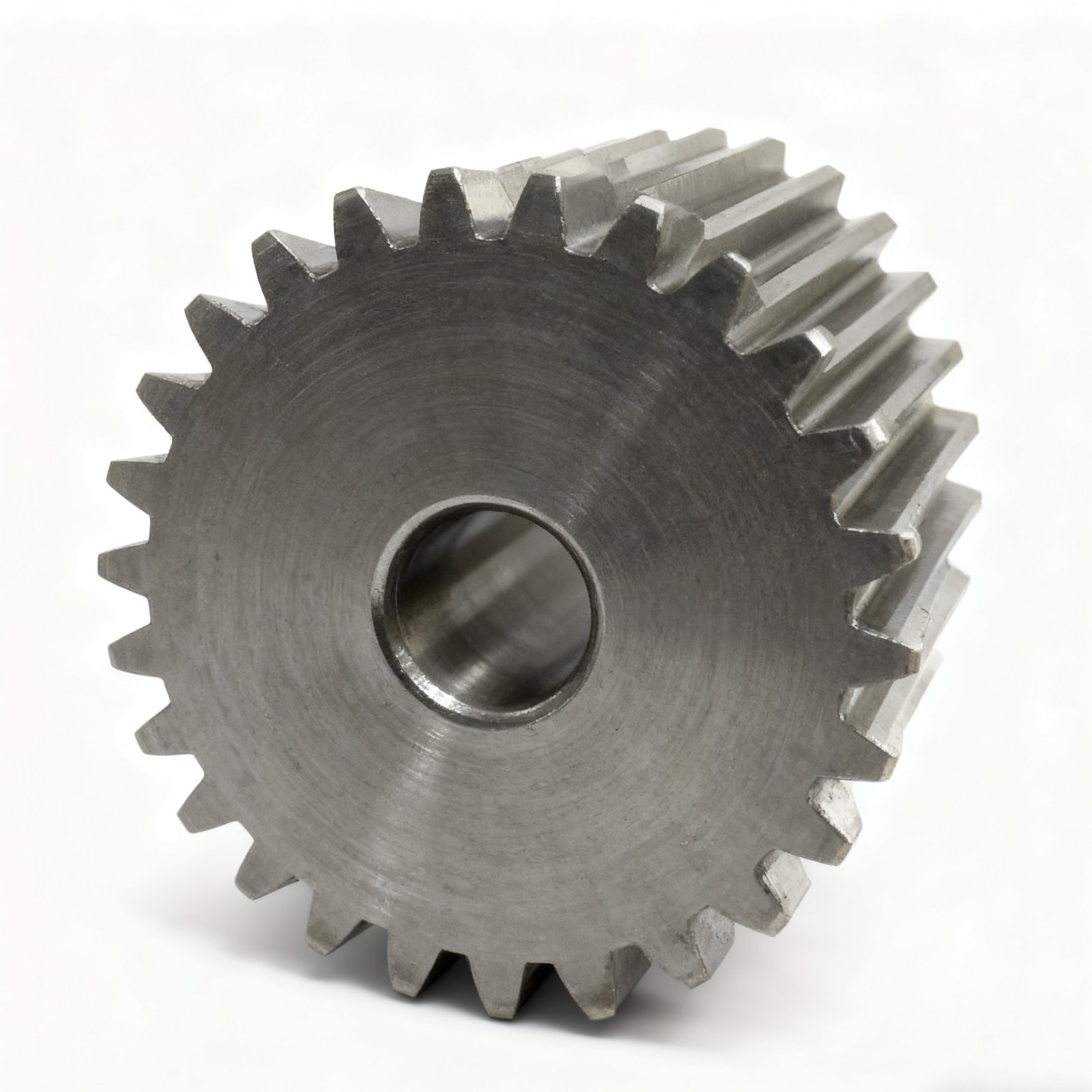
Steel spur gear, teeth in the state after hobbing/milling, inner bore already machined
Inspection after hobbing or shaping focuses on the two types of quantities that directly affect meshing: tooth thickness and runout:
| Inspection item | Requirement | Tool |
|---|---|---|
| Base tangent length (Wk) | Per drawing | Base tangent micrometer |
| Tooth thickness | Per drawing | Tooth thickness caliper |
| Gear ring radial runout (Fr) | ≤0.05 mm | Runout fixture + dial indicator |
| Tooth surface roughness | Ra ≤3.2 μm | Roughness comparison block |
| Tooth end deburring | Uniform chamfer | Visual |
Base tangent length is the most sensitive drift indicator for hobbing: tool wear, machine thermal deformation, and workpiece deflection almost all show up on it first, so it is usually measured every 50 pieces and recorded in an X-R control chart, looking at the trend rather than only the single value.
III. Heat treatment and gear grinding: the two processes that cannot be fixed afterward#
Heat treatment is the only process that “cannot be changed once done.” Insufficient hardness can be re-quenched, but decarburization, cracks, and out-of-tolerance deformation often lead directly to rejection.
| Inspection item | Requirement | Tool |
|---|---|---|
| Surface hardness | 58~63 HRC | Rockwell hardness tester |
| Core hardness | 30~42 HRC | Rockwell hardness tester |
| Effective case depth | 0.8~1.5 mm (per drawing) | Vickers hardness tester / metallography |
| Surface decarburization | Not allowed | Metallographic microscope |
| Deformation | ≤0.10 mm | Inspection platform + dial indicator |
| Cracks | Not allowed | Magnetic particle inspection |
Heat treatment is managed by furnace batch; each furnace batch retains the loading method, temperature curve, quenching medium, and sampling results. If sampling in the same furnace fails, the whole furnace is reviewed — locking the risk within the furnace batch range is more realistic than full inspection piece by piece.
Gear grinding is the last step to bring up precision, and its inspection requirements are also the most detailed:
| Inspection item | Requirement | Tool |
|---|---|---|
| Total cumulative pitch deviation (Fp) | ≤25 μm | Gear measuring center |
| Tooth profile deviation (Fα) | ≤10 μm | Gear measuring center |
| Helix deviation (Fβ) | ≤10 μm | Gear measuring center |
| Radial runout (Fr) | ≤15 μm | Gear measuring center |
| Tooth surface roughness | Ra ≤0.8 μm | Roughness tester |
| Grinding burn | Not allowed | Acid etching inspection / visual |
| Base tangent length (Wk) | Per drawing | Base tangent micrometer |
The first piece of gear grinding goes to the gear measuring center for a full report, after which every 50 pieces are sampled. Grinding wheel wear brings slow changes in tooth profile shape, which cannot be caught by base tangent length alone; these deviation items must go to the measuring center.
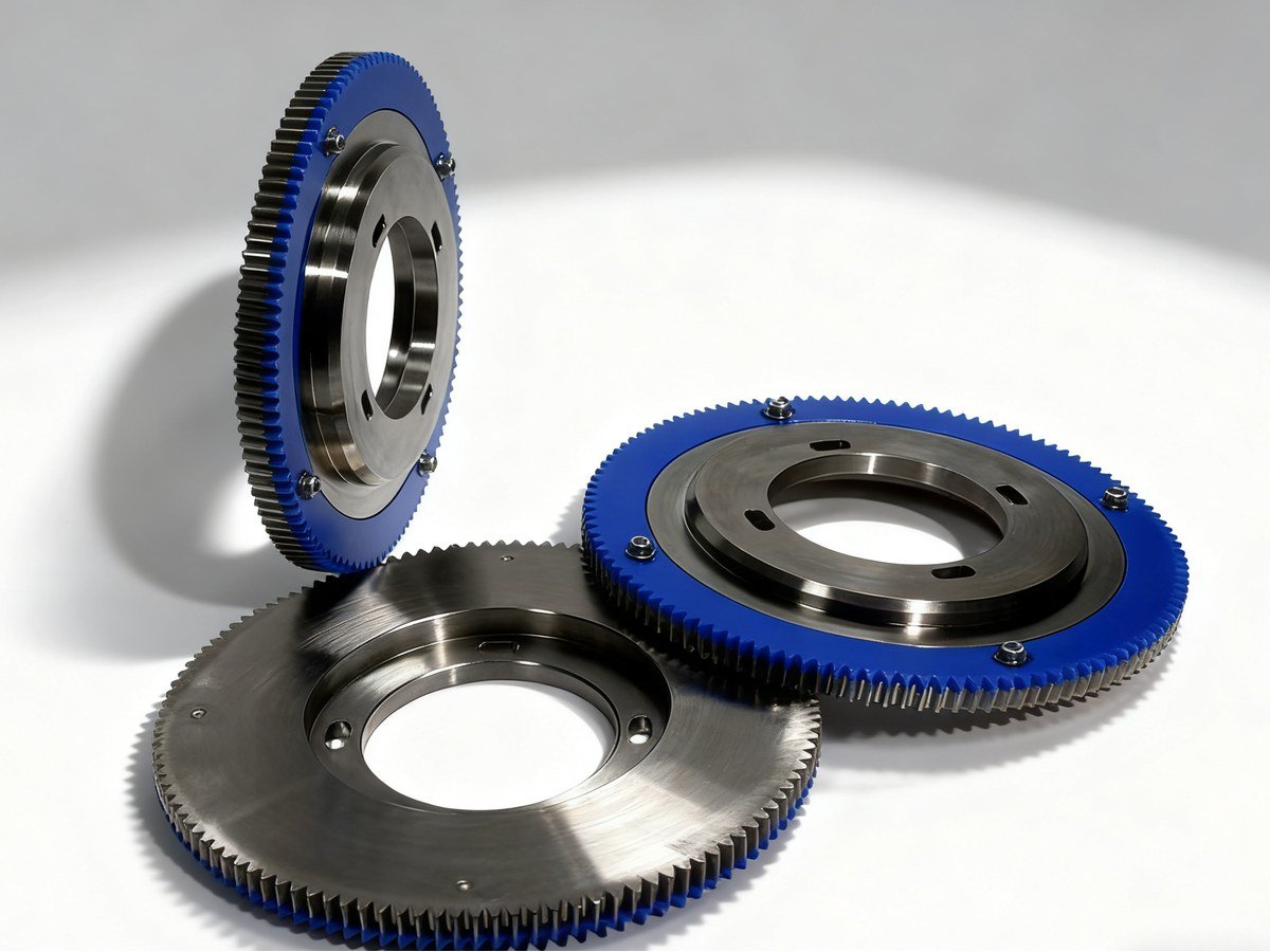 Three large-diameter thin-wall external ring gears, teeth in the state after finishing, end face with mounting threaded holes
IV. Handling sequence after an anomaly occurs#
- Operator finds an anomaly in self-inspection → stop the machine → notify the inspector → trace and investigate the previously machined pieces;
- Inspector finds an anomaly during patrol → attach a “production suspended” sign → notify the team leader or workshop supervisor → review and handle;
- First piece unqualified → adjust or dress the equipment → redo first-piece inspection → continue production only after qualification;
- Batch unqualified → transfer to the nonconforming product handling process, isolate, review, and determine repair or scrapping.
The key lies in the tracing in the first step: after stopping the machine, it must be possible to answer “how many pieces have been machined in total from the last qualified piece to now.” This requires continuous inspection records — the inspection time, piece number, and measured values of each shift are all on file. Once the records have a gap, tracing can only be expanded to the entire shift, and the loss is amplified.
Record retention periods also differ: process records for rough turning, shaving, and drilling are kept for 3 years; the X-R control charts for hobbing, heat treatment furnace batch records, and gear measuring reports for gear grinding are kept for 5 years. For export orders or customer second-party audits, this set of records is the most direct evidence.
V. How to connect with upstream and downstream#
In-process inspection connects upstream to incoming inspection and downstream to outgoing inspection. Incoming inspection controls material and allowance (see What Precision Gear Incoming Inspection Checks), in-process inspection controls the drift of each process, and outgoing inspection controls appearance, marking, and accompanying reports — the three segments connected together form a complete quality chain. Geyon Transmission’s inspection system covers cylindrical gears, bevel gears, and worm gear sets with module 0.5~20; after gear grinding, pitch, tooth profile, and helix are each output item by item on the gear measuring center.
Have a batch of gears or ring gears that needs stable delivery, and are unsure how to set the inspection checkpoints and sampling frequency? Send over the drawings and batch quantity; the engineering team will first conduct a drawing review, then provide a written plan for the process route, inspection items, and permissible deviations. Request a gear machining quote.