
How Far Gear Inspection Can Go: Capability Boundaries and Three Routes Beyond Scope
Gear inspection limits: cylindrical gears module M 0.5–20, OD 10–800 mm, ≤300 kg; pitch deviation Fp ≤100 μm; hardness 20–67 HRC; case depth per ISO 2639.
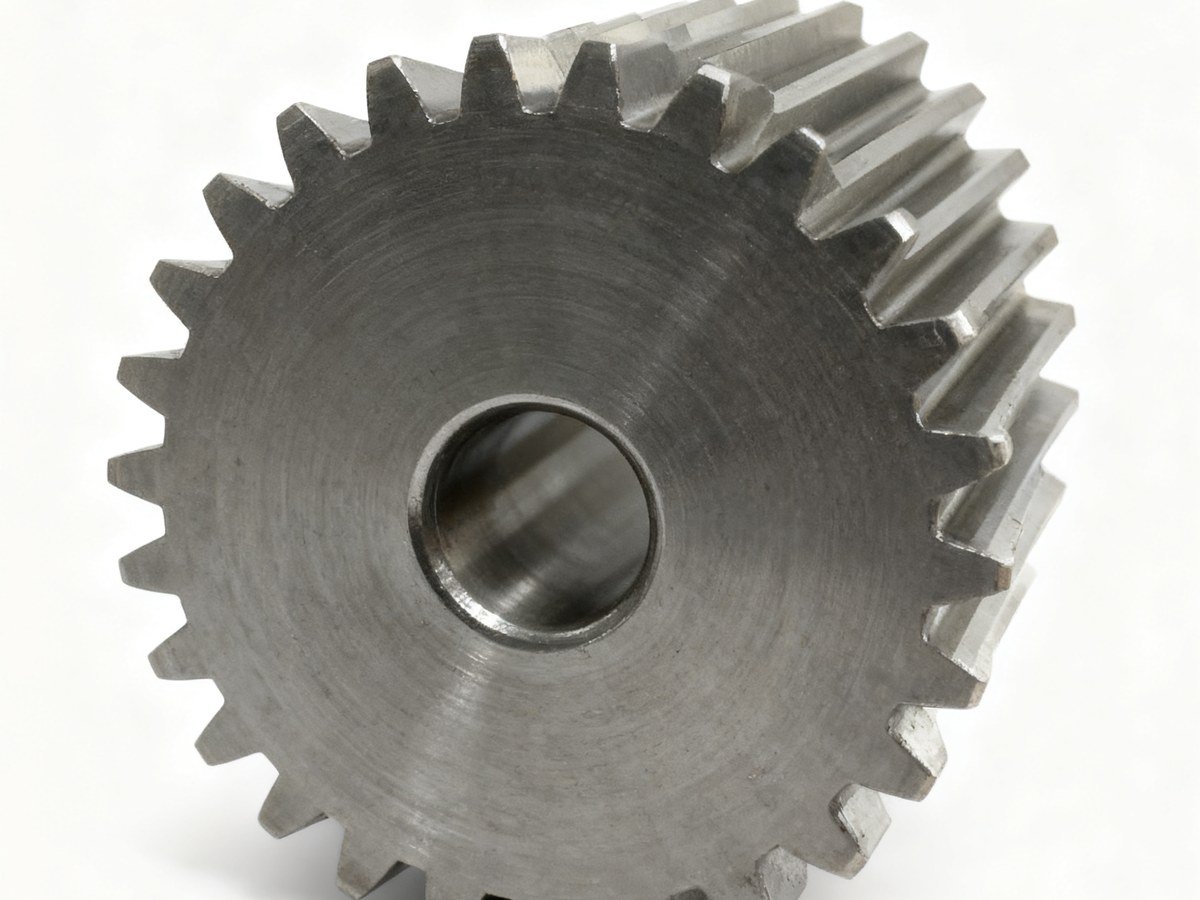
How Far Gear Inspection Can Go: Capability Boundaries and Three Routes Beyond Scope
Before sending a drawing over, there is one thing worth checking first: whether this part can go on our measuring instruments at all. Gear inspection is not a checklist that says “we can measure anything”; it is bounded by maximum size, maximum weight, measuring range and accuracy limits. Making this boundary clear before quoting is more useful than seeing a column of numbers in a report — because items beyond the boundary are handled in a completely different way.
1. First, check whether the workpiece fits on the table#
The first limit is the workpiece itself. With the current equipment configuration, the coverage for several common types of gear parts is as follows.
| Workpiece type | Coverage |
|---|---|
| Cylindrical gears (external / internal teeth) | Module M 0.5~20, outside diameter 10~800 mm, face width ≤400 mm, workpiece weight ≤300 kg |
| Bevel gears | Module M 1~16, maximum diameter ≤500 mm, pitch cone angle 5°~90°, tooth surface contact pattern and meshing noise measurable |
| Worm gears and worms | Worm module M 0.5~16, number of worm starts Z 1~6, maximum worm wheel outside diameter ≤800 mm |
| Splines | Rectangular / involute / triangular splines, module M 0.5~8, major diameter 10~300 mm, flank centering accuracy ≤0.025 mm |
The figures in the table are the limits for “can be clamped, can go on the machine, can produce data”, not the limits of machining capability. For ring gears over 800 mm and gear shafts weighing more than 300 kg, machining can be done, but inspection requires another approach; see Section 5 for the handling paths.
2. Within what range does each deviation have data#
What is actually looked at in a gear report is the deviation items, not the external dimensions. The measurable ranges are listed by item:
| Inspection item | Capability range | Remarks |
|---|---|---|
| Total cumulative pitch deviation Fp | ≤100 μm | ISO/DIN grades 5~8 |
| Single pitch deviation fpt | ≤20 μm | |
| Profile deviation Fα | ≤15 μm | |
| Helix deviation Fβ | ≤15 μm | |
| Radial runout Fr | ≤50 μm | |
| Variation of base tangent length Fw | ≤30 μm | |
| Tooth thickness deviation Esn | ≤50 μm | |
| Worm axial pitch deviation | ≤12 μm | Worm parts |
| Worm tooth profile tolerance | ≤10 μm | Worm parts |
One thing needs to be made clear: these are the instrument’s measuring range and achievable accuracy, not acceptance criteria. Acceptance is judged according to the ISO/DIN grade marked on the drawing; the report is only responsible for measuring the actual values and providing the curves. If the drawing specifies grade 6 and the measured values fall within the grade 5 range, the judgment is still “drawing requires grade 6, measured grade 5” — the stated basis will not be changed just because the numbers look good.
3. Hardness: choose the wrong method and the numbers are not comparable#
The same gear measured by different hardness methods will give different values, and the magnitudes differ as well. Capability ranges are divided by method:
| Inspection type | Standard | Measuring range | Applicable workpieces |
|---|---|---|---|
| Rockwell hardness HRC | GB/T 230 / ISO 6508 | 20~67 HRC | Hardened gears, shafts |
| Rockwell hardness HRB | GB/T 230 / ISO 6508 | 40~100 HRB | Annealed parts, non-ferrous metals |
| Brinell hardness HBW | GB/T 231 / ISO 6506 | 8~650 HBW | Blanks, forgings, castings |
| Vickers hardness HV | GB/T 4340 / ISO 6507 | 10~1000 HV | Carburized layer, thin-walled parts |
| Superficial Rockwell HR15N | GB/T 230 / ISO 6508 | 70~93 HR15N | Carburized and hardened surface layer |
It is common for the drawing to specify HRC while the report gives HV, especially for carburized parts — when thin walls or tooth flanks do not allow a deep indentation, only Vickers can be used. Conversion between the two is acceptable as a reference, but for arbitration one must return to the method specified on the drawing and the corresponding standard.
4. Dimensional metrology, roughness and material analysis#
In addition to gear-specific deviations, reports often include dimensional metrology and material items:
- Dimensions and form/location: shaft diameter 0.5~800 mm (±0.002 mm), bore diameter 0.5~600 mm (±0.002 mm), length 0.5~1000 mm (±0.01 mm); roundness ≤1.0 μm, cylindricity ≤2.0 μm, face and radial runout ≤2.0 μm, coaxiality / position / parallelism / perpendicularity ≤5.0 μm, flatness ≤3.0 μm.
- Surface roughness: Ra 0.01~20 μm (resolution 0.001 μm), Rz and Rmax 0.1~100 μm.
- Metallography and material: carburized case depth and effective hardening depth (GB/T 9450 / ISO 2639), martensite grade and retained austenite content (GB/T 25744), chemical composition spectral analysis (GB/T 4336 / GB/T 223), surface and internal defects (ultrasonic / magnetic particle, GB/T 7233 / GB/T 6402).
5. Three paths after going beyond the range#
When a workpiece exceeds the ranges in the tables above, it does not end with “cannot be measured”; usually one of these three paths is taken:
- Outsource to a third-party laboratory. For large ring gears, very large measuring ranges or special items, send to a laboratory with the corresponding qualification, and the report is delivered with the goods. Lead time and cost are listed separately and must be stated clearly when quoting.
- Change the measurement plan. If a full-item scan on the gear measuring instrument is not possible, it can be broken down into individual items: base tangent length, span over balls, tooth thickness and runout measured separately with fixtures and universal measuring tools, covering the items that are actually judged on the drawing. The accuracy limit will be lower, but data can be obtained for the key items.
- Change the datum or the structure. For some parts the difficulty is not the size but the absence of a usable measurement datum. Adding a process datum face on the drawing, or splitting an integral part into components (ring gear + hub), restores measurability. This one must go into the drawing review and cannot be left until before delivery.
All three must be stated clearly at the quotation stage. The most expensive mistake with gear parts is not that they cannot be measured, but that this is only discovered at delivery.
6. Prerequisites for the data to be valid#
Two conditions must be stated on the report: inspection is carried out in a standard environment (20±1 ℃), and all equipment is within its valid calibration period. In addition, gear grinding and inspection must use the same set of locating datums — when the drawing does not clearly state which face is used for location, the helix data will not match the actual meshing condition in the housing, and offset load will appear in the form of “gear qualified, assembly has a problem”.
Geyon Transmission undertakes the manufacture and inspection of precision gears and transmission parts, covering gear grinding to DIN/ISO grades 4~5. Send over the drawing (module, number of teeth, accuracy grade, material and hardness requirements); we will first carry out a drawing review to confirm the measurable items, the measurement plan and the required report scope, and then quote for machining and inspection.
- Inspection items and report scope: Quality and Inspection
- Spur gear / helical gear machining: Precision Gear Manufacturing
- Submit a drawing for quotation: Get a Gear Quote